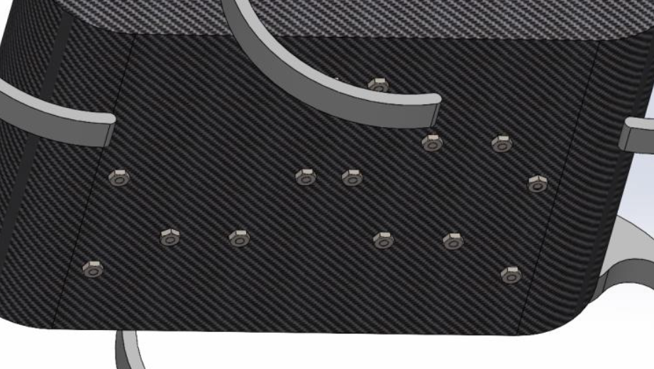
Rhex robot
Completed in Dec 2022

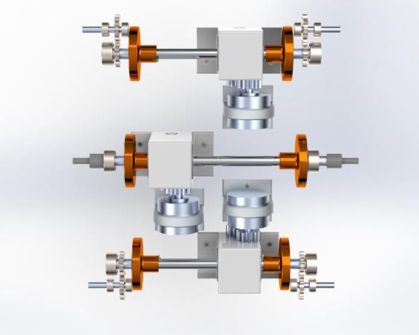
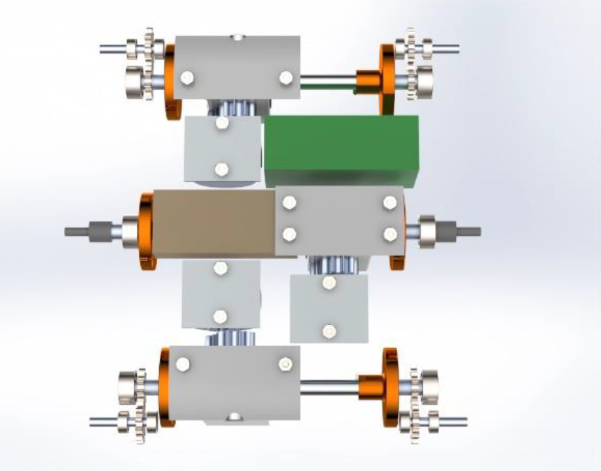
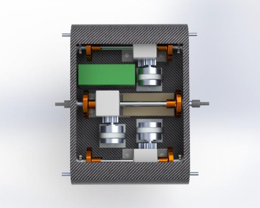


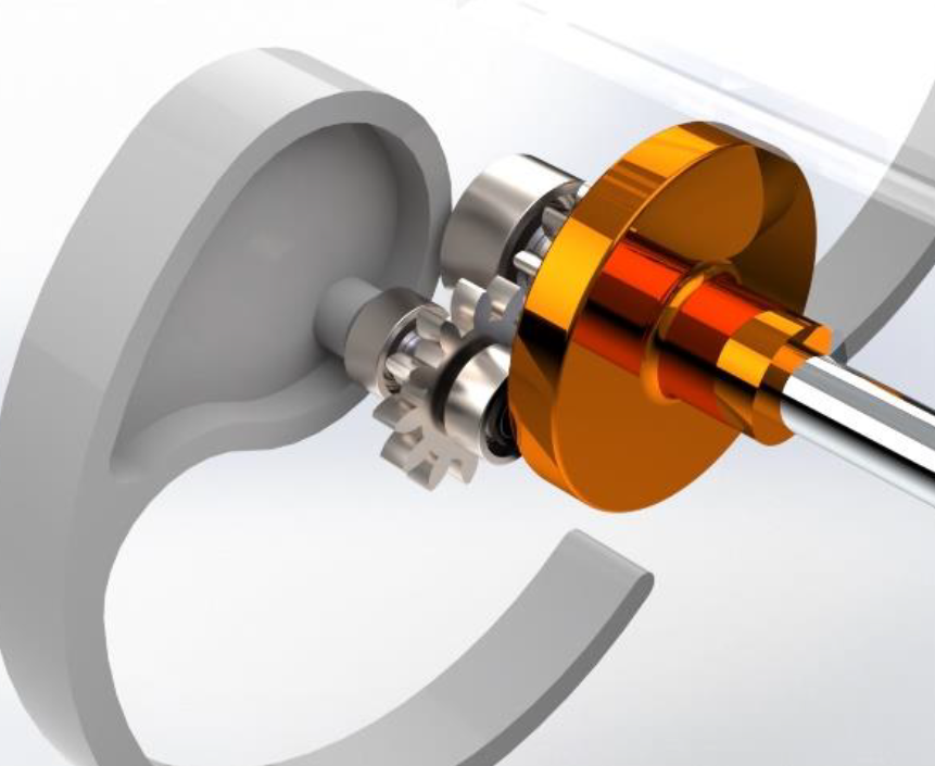
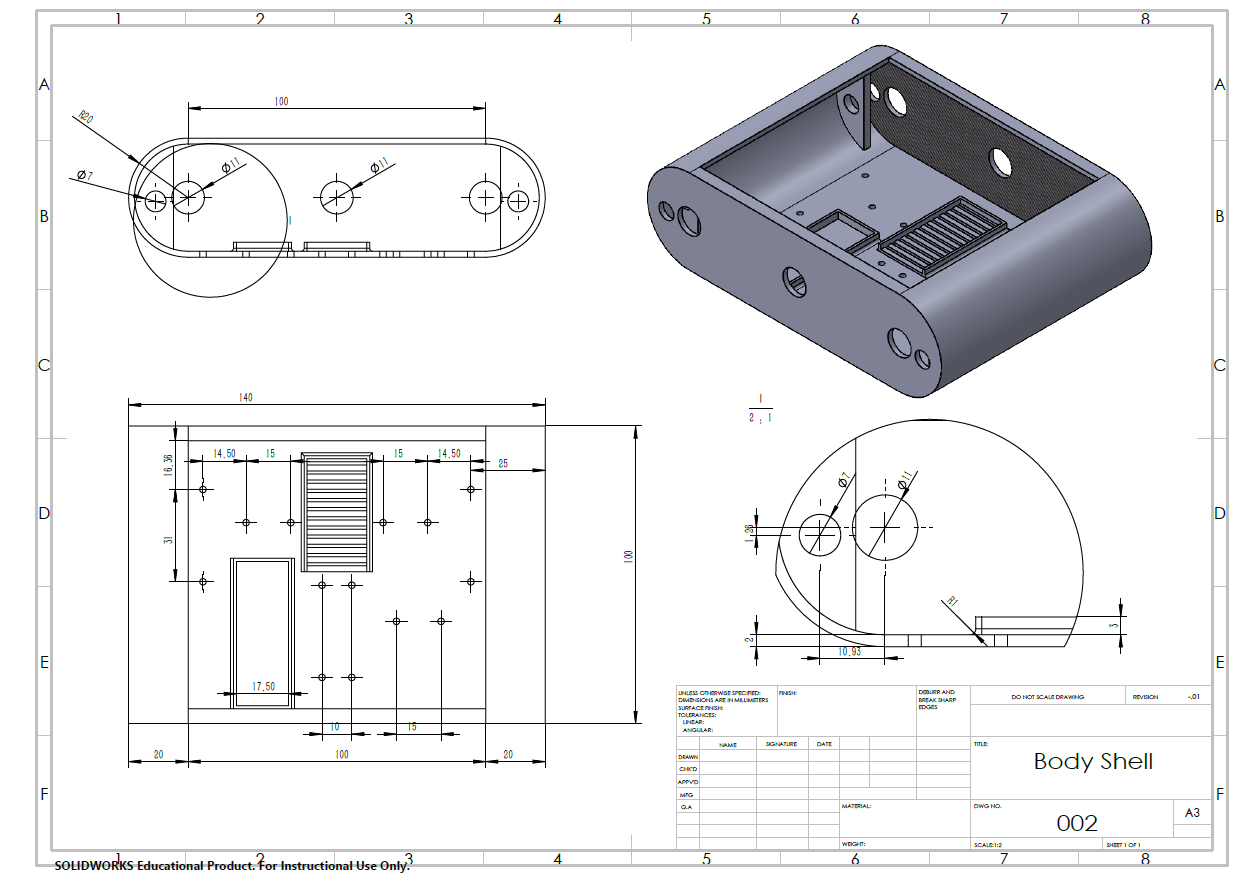
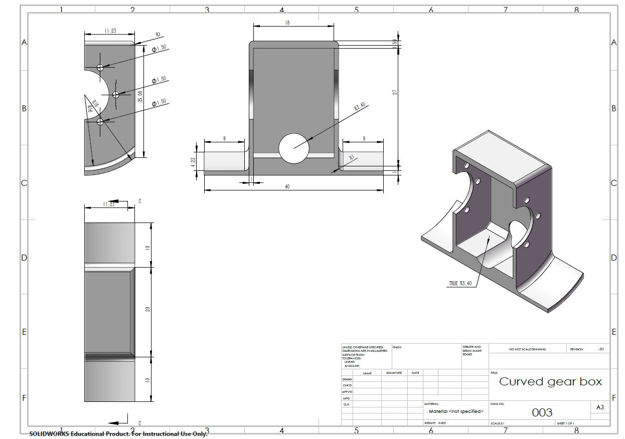
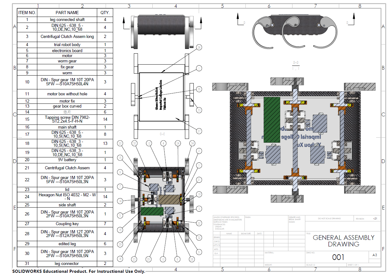
The Gizmo Rhex robot project designed a 3D structure robot with certain functionalities such as high wall climbing and fast walking, using Solidworks and Ansys. Expenses are controlled in 200 pounds by considering industrial standard components and material cost.
Design Target
There are three main ufnctionality requirements of the robot:
Climb a 20 cm high vertical wall
Turning with turning cycle less than 165mm
Fast walking with speed more than 0.5m/s
This gives restrictions on motor and structure design.
Detailed to components
Motor has a minimum torque of 0.29Nm
Rotating speed higher than 6900rpm
Open loop system (limited budget)
EC motor
9V battery
Structure design
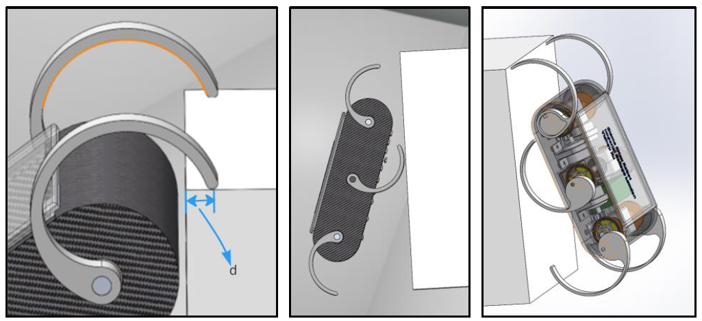
Half cycle leg doesn’t suffer from the discontinuity, and it also allows for effective touch down and lift-offs.
To enable successfully climbing, the front wo arms are designed to be flipped in direction to the left four legs. They act as sprawl to contact he top surface and lift up the body. More than 180 degree arc would create shorter distance between the contact point and the edge of the 20cm stage, as seen below. Therefore the shape is design to be half arc.
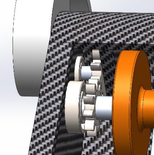
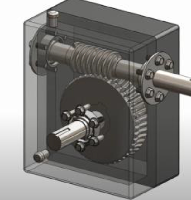
However, the leg length has its maximum value due to project requirements. To climb the stairs, even the body is completely vertical and attached to the wall, there is still a 5mm gap. Therefore, the centre of rotation has changed closer to the edge by having extra gears added inside the body. The gear ratio is 4 to 4.8 which also provides an increase in torque.
Furher design details
Failure analysis with Ansys
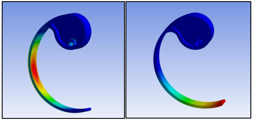
The maximum equivalent stress is 37.8MPa, the maximum total deformation is 40mm. The structure is shown to be very easy to break in the middle of the curve. The equivalent stress is beyond ABS’s tensile yield strength. Therefore, the thickness of the leg is enlarged, and the fillet between the cycle and thin legs are increased as well. By reducing the thin layer length and add 1mm of thickness, the maximum tensile strength is restricted below 16.12MPa, and the maximum total deformation became 11.6mm, which offer wider range of other material selection in the future.
Equivalent stress diagram (left) Total deformation diagram (right)
Leg after editing (left) Ansys analysis of edited leg (right)
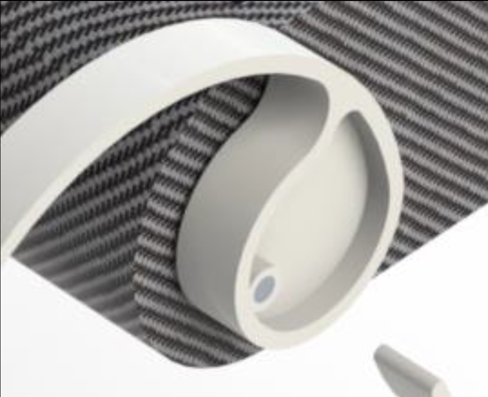
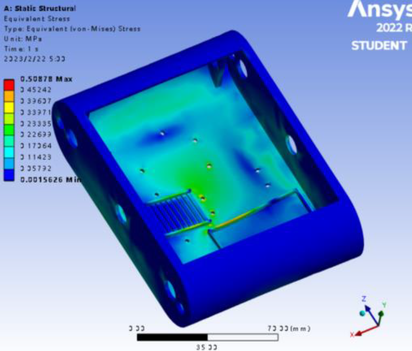
Similarly, the bottom part is strengthened by having nuts closely attached to the hole, fix with screws in the middle. A 2mm expansion in width distribute the stress and help robot stay more rigid.


